|
Wow,
are we electrified today
When the
motor tends to start bad, usually the ignition is responsible. There
are many cars out there where the ignition wasn't adjusted since
centuries. To get the motor back into the real life it is
recommendable to begin the maintenance work with an ignition job.
We will start here with some theory to understand how the ignition
works - it's not only mystery.
How a spark is created
To create an electric spark, we need a very high voltage - up to
20,000 Volt. The alternator in the car delivers only 12V. To reach
this high voltage we have to use a trick - a coil is used. An electric
current is sent through the coil, which creates a magnetic field like
an electric magnet. This magnetic field is nothing but stored energy.
To convert this energy back in electricity we have to interrupt the
current. This is the job of the points. Now we could start to
calculate the level of the voltage due to the inductivity formula - or
we can simply forget about it. The physical effect can be simplified.
Whenever the strength of a magnetic field in a coil changes, it
induces an electrical current in the coil. When the magnetic field
increases, the resulting current itself creates a magnetic field that
is weakening the initializing field. If the magnetic field is reduced,
the resulting current creates a field that tries to keep the original
field up. When the points open the initializing current will stop.
This makes the magnetic field collapsing completely. The result should
be a current. But since the points are open, no current can flow. This
makes the voltage rise high. The coil is also a transformer. The ratio
between primary and secondary side is very high. If the ratio is 100
this means that a voltage of 200V on the primary side will be
transformed to 20,000V on the secondary side.
When the voltage is high enough, a spark fires on the spark plug.
With the spark we have a current again. This means the stored magnetic
energy is now converted back into electrical energy.
Together with the condenser the coil creates a resonance cycle. The
energy will now be transferred from the coil (magnetic) into the
capacitor (electric) and back. The spark burns until the energy
transfer between coil and capacitor runs out.
Now to the practical use
For the ignition we have to adjust 2 parameters. The time while a
current will charge the coil with magnetic energy - the dwell, and the
moment when the spark should fire inside the cylinder - the timing.
The compressed gas needs some time to ignite. As soon as the piston
reaches the upper dead center the explosion is needed to drive the
piston down again. To compensate the delay between the moment of the
spark and the moment for the gas to burn completely, the spark has to
be sent a bit earlier. The right moment to fire the spark is 8°
before the piston reaches the upper dead center.
When the motor runs faster, the time it needs to turn 8° is
shorter. Since the time between the spark and the explosion is almost
constant, the spark needs to be sent a little earlier depending on the
speed of the motor. To compensate for this the motor needs a dynamic
pre-ignition. In the 2CV motor this adjustment is done via the cam
advance weights. Due to the speed of the camshaft the weights will be
pulled out turning the cam, which changes the angle to the direction
of advanced timing.
Adjustment
To replace and adjust the points the fan has to come off first. The
cooling fan grill usually doesn't create problems. The fan pulley is
held on the crankshaft by one bolt size 14mm. You have to find a tool
that fits into the fan pulley to undo the bolt. With a little luck
your 14mm socket will already fit. To undo the bolt the motor must be
blocked. A screwdriver held into the gear on the flywheel can easily
do this. Once the motor is blocked it is easy to undo the bolt. Mostly
the fan pulley sits very tight on the crankshaft. The front end of the
shaft has a cone shape, which makes the fan pulley to sit even
tighter. To pull it off Citroën had a special tool in the
catalog. Unfortunately the tool did not work proper and it isn't
available anymore since many years. A better way to get the pulley off
is a simple steel pin, which is turned down to the diameter of the fan
pulley. 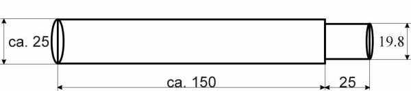
Sketch for tool;
dimensions in mm
For
removal, the fan pulley has to be positioned in a way that the claws
for the crank handle are located horizontal. The pin now goes into the
pulley. Hold the pin firmly and smack it with a hammer. Don't hit too
hard - remember this is the front end of the crankshaft! Hit the pin
as close to the inside as possible. Mostly two or three smacks should
do. It is recommendable to use this pin and no other tool like a
socket extension. If the pin doesn't fit proper it means that you have
to hit too much on the crankshaft to get the pulley off.
To dig down to the points housing the rubber cover has to be removed.
Behind the cover you will find the points housing. 3 bolts attach the
lid. Undo the lid to get access to the points. Before you undo the
bolts holding the points housing you should loosen the 2 bolts holding
the capacitor and the static part of the points. When these bolts are
loose and the 2 7mm bolts are out you can finally take out the points
housing. It will come out best when you lever it out with a
screwdriver on the upper corner. 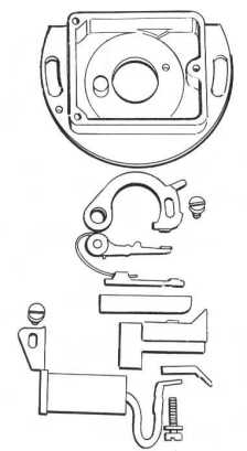
Components of
points assembly
Now the
cam stands free. Take out the protective cover behind the cam to check
the advance weights. Both ends of the weights should not be worn out.
Check if you can twist the cam up to the limiter for the weights. It
needs to work without any play in the weights. Check if the cam is
worn on the surface from the nylon block on the points. After some
time the nylon runner may mill its way into the cam. If the cam or the
weights are worn they have to be replaced. When all is ok here, just
clean everything and put the cover back in.
Now you start with the points housing. Take the old points out.
Always replace the points when you get that far, even when the points
are only a little worn.
Check the surface of the old points. Both contacts should be worn
parallel. If you find a spike on one end and a crater on the opposite
side, the capacitor needs to be replaced. Due to the direction of the
spike you could even detect if the capacity is too high or too low.
For us this is irrelevant - wrong capacity means to replace the
capacitor. In return this means that the capacitor doesn't always need
to be replaced. A few times I faced the problem that a brand new
capacitor was defective. This is a very unpleasant thing to happen.
The just replaced part is the least you expect to be defective.
Before you start mounting anything - clean the points housing and all
related parts. Usually everything is covered with a yucky layer of
dirt and oil. The next step is to check if the pin that works as an
axle for the points is still tightly riveted to the housing. Sometimes
this pin comes loose and swivels around. You may not realize this but
it makes it impossible to adjust the ignition proper. Check if you can
twist or move the pin in any direction. It must not allow you to be
moved in any way. If you find the pin loose, you may try to hit the
back of the pin with a center punch in order to reinforce the riveted
connection. Mostly this attempt fails and you need to replace the
points housing - but you have nothing to loose. I would give it a try.
To assemble the points, always mount the non-moving part first. Use
the correct bolt to attach it to the back plate of the housing. The
bolt has a thick washer and one thin washer. If you use a different
bolt or leave out the washers, the bolt will stick out to the back and
catch on the advance weights. To avoid this damage, always use the
correct bolt and washers!
Assemble the moving part of the points with the tension spring, put
it into the plastic insulator and mount it into the points housing.
The condenser is mounted in its plastic bracket and bolted onto the
points housing. I always replace the bolt and the tension washer that
connects the +12V from the tongue connector to the inside onto the
points. This is a simple 4mm steel bolt that tends to rust. Once the
surface is rusted, the bolt develops an electrical resistance. This
may cause problems reaching from unwilling behavior starting the car,
up to a total failure of the ignition system. This can be avoided by
replacing the bolt with a stainless steel bolt and tension washer. I
had this effect once on one of our own 2CVs. The car didn't start at
all. The search indicated that we had +12V on the connecting tongue
outside of the points housing, inside was nothing. The rust had
totally insulated the metal connection. The stainless bolt avoids this
problem for once and all. Even if the bolt doesn't completely
insulate, the 2CV will still start and run but the performance goes
down. If you use an electronic ignition system that is controlled by
the points, the system might fail already.
The assembled points housing goes back into its place in the
crankshaft housing. Don't forget to re-connect the wire. The next step
is to adjust the dwell and the timing. TIP: To crank the engine easy,
just insert the bolt that was holding the cooling fan directly into
the crankshaft. Once the bolt is tight, it allows you to turn the
engine very easy by hand using the 14mm wrench.
There are two ways to adjust the ignition: The static adjustment as
Citroën describes it in the manuals - and the more accurate
dynamic adjustment with a dwell meter and a timing light.
First the description of the static adjustment
The dwell-angle is related to the gap. So to adjust the dwell-angle,
you actually set the gap between the static and the moving part of the
points. Turn the engine to the position where the camshaft fully opens
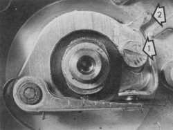
the points. Open bolt No. 1 (See photo) just enough to allow the
static part being moved up and down. Use a feeler gauge to adjust the
distance between the contacts to 0.4mm by turning the static part up
or down. You can open or close the gap by twisting a screwdriver
between the points housing and the adjuster nose on the points (See
photo, mark No. 2). 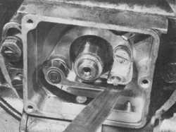
Adjust the dwell
angle with a feeler gauge
Once you
have reached the correct gap, the feeler gauge must just fit in the
gap - it shouldn't be loose and it shouldn't push the moving part of
the points away. Tighten bolt No.1 and turn the engine to open the
points from the cam on the opposite side. Check the gap in this
position. The difference must be 0.05mm or less. If you find a bigger
difference you have to replace the cam.
Adjust the dwell
angle
The
flywheel must be in the right position to adjust the timing. To find
the right place, the flywheel has a 6mm hole. The corresponding hole
in the crankcase is in the upper motor mount on the driver's side.
Lock the position of the flywheel by engaging a 6mm pin through the
hole in the crankcase into the hole in the flywheel. You can easily
make this pin yourself (See diagram). Once the pin is engaged, the
flywheel is locked in the 8° position before upper dead center.
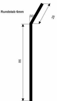
Locking pin for
timing adjustment; dimensions in mm
This is
the exact position where the points have to open. Use a simple
automotive test lamp to check the current. Connect the test lamp
between the negative side of the coil (The wire that connects down to
the pints housing) and ground (The alternator supplies a good ground
connection). As long as the points are open, the light will be on.
Once the points close, the current is bypassed through the points -
the light shuts off.
This is the exact position you have to adjust. Twist the points
housing in its seat to reach the position where the light can't really
decide if it is on or off - the slightest touch should now turn the
light on or off. To enable the points housing to me twisted in its
seat, the 7mm bolts that hold the housing, must be slightly open but
not loose. To turn the housing you can smack it carefully on the upper
corners - preferably with a piece of wood (hammer handle) or plastic
(screwdriver handle). This way you avoid damaging the aluminium
casting.
Tighten all bolts when the adjustment is done. Don't forget to check
again - quite often the adjustment changes a little while you tighten
the bolts - and very important: Check everything on the opposite cam.
All this sounds simple but in real life with twisting the points
housing, you also change the dwell again. Adjusting the dwell will
change the timing. It sounds like Catch 22 but with every adjustment
cycle you get closer to the correct position. Depending on your skill
you have to adjust dwell and timing a few times before the setting is
ok.
VERY IMPORTANT: Don't forget to remove the pin from the flywheel when
you are done. If you try to start the motor with the pin still
engaged, the pin will bend which makes it sometimes impossible to
remove it from the crankcase!
Dynamic adjustment
The dynamic adjustment is much quicker to accomplish and also more
precise than the static adjustment. When the 2CV was designed there
were no timing lights available so Citroen made no mark on flywheel or
crankcase. This leaves it up to you to make a mark. Block the flywheel
with a 6mm pin as described above. This position represents the
correct timing. Now paint a mark on the flywheel. I always use
correction fluid for paper. The bottle comes with a little brush on
the inside of the lid. This makes it easy to paint a line on the
flywheel. Furthermore, the paint is white which makes it better
visible using the timing light.
It's up to you where you apply the mark. I always set it to the left
side of the starter motor (passengers side). It is important that you
don't mark the flywheel opposite to the left mounting arm on the
crankcase. This place is tempting since you can paint a static mark
onto the crankcase. But keep in mind the once the motor runs, the
advance weights kick in and move the mark to the left - hiding it
behind the crankcase mounting arm. Not seeing the mark isn't really
helping in your attempt to adjust the timing.
In comparing the position of the mark after a precise static
adjustment with the dynamic method, I determined the position for the
mark offset by one tooth to the left on the flywheel. I did this in
many motors and all of them showed the same deviation.
To do the entire adjustment with the motor running, you need a
suitable measuring device. You can buy a dwell meter and a timing
light separate. I found a timing light with a built in tachometer and
a dwell meter. The instrument isn't as precise as the professional
computer test centers that modern cars need - but working on a 2CV
isn't quite rocket science after all. This instrument was very helpful
for me over a long period of time. If you like to purchase this
convenient instrument see "2CV Accessories"
To prepare for the adjustment you have to mount the points housing
horizontally. Adjust the gap to roughly 0.4mm (0.0157"). Mostly
this is enough to start the motor. The motor must be running for the
dynamic adjustment. If it wouldn't start so far you have to do a rough
static adjustment to allow the motor to start.
The final adjustment is done with the clever instrument. The red and
black clips are for the supply voltage: Red is +, black is -. The
green clip is connected to the coil, picking up the interrupted signal
from the points, so it must be connected parallel to the wire leading
from the coil down to the points. The inductive sensor is put around a
spark lead. It doesn't matter which one. The 2CV fires sparks on both
sides simultaneously, so both spark leads carry the same signal.
Keep in mind that the gauge for dwell and tachometer is for
4-cylinder motors. This means that it shows only half the reading for
the 2-cylinder 2CV motor. Just double all readings. The correct dwell
angle is 108º - 109º. Adjust the dwell to a reading of 54,5º
on the gauge. The dwell stands for the ratio between the points being
closed and the points being open. This ratio is determined by the
shape of the cams and theoretically remains the same over all speeds.
In practice you will see the needle display a different value at a
certain speed. Adjust the dwell at idle and check your adjustment at
different higher speeds.
Once the dwell is correct, adjust the timing. The motor must idle
with 800 Rev/Min. Check the idle speed with the built in tachometer.
The 4-cylinder gauge must read 400. It is important that the speed is
correct. If the motor turns faster, the dynamic timing advancement
will kick in. At 1500 Rev/Min the advance weights are already at their
maximum position, which makes it impossible to adjust the timing
correct. Adjust the speed on the carburetor. Turn the adjustment screw
for idle speed outwards. If the motor is too slow you may use the
choke to increase the speed to 800 Rev/Min.
When the timing is set correct the white mark on the flywheel should
show one tooth left from the theoretical static position.
If the cams are worn uneven or if the front of the camshaft is bent,
you will see two marks in the flash of the timing light. A distance of
3º - equal to one tooth can still be tolerated. In this case
adjust the center between the marks to the correct position. When the
distance between the marks is bigger than 3º check and replace
the cams if necessary.
Check the dwell as it may have been changed again. If so do the dwell
and timing adjustment again until both are correct. Tighten both bolts
holding the points housing and the bolt that secures the points when
both adjustments are satisfying. Finally check again if something
changed from tightening.
IMPORTANT: As long as the motor runs during the adjustments it
operates without cooling - the fan is missing! An air-cooled motor
without fan and no cooling air from driving can easily overheat and be
damaged. Citroën stated that the motor might not be operated
without cooling for longer than 10 minutes. I think this time is way
too long. The adjustment should be done in 2-3 minutes. Once the
adjustment is done shout the motor off immediately!
When all was adjusted and checked it is time to re-assemble
everything. Install the lid of the points housing with the rubber
gasket in place. Cover everything with the rubber protector. Use
grease on the 5mm bolts holding the protector. Before you mount the
fan pulley check the condition of the fan belt. It shouldn't show too
many cracks. Than check the oil cooler. The cooling fins must be dry,
clean and undamaged.
Put the fan belt into its groove on the fan pulley and mount the
pulley on the camshaft. Tighten the bolt in the fan pulley. To block
the flywheel use a screwdriver in the gear - like for the disassembly
before.
Finally mount the cooling fan grill - use grease on the 7mm bolts.
Now lean back and relax - you are done. |